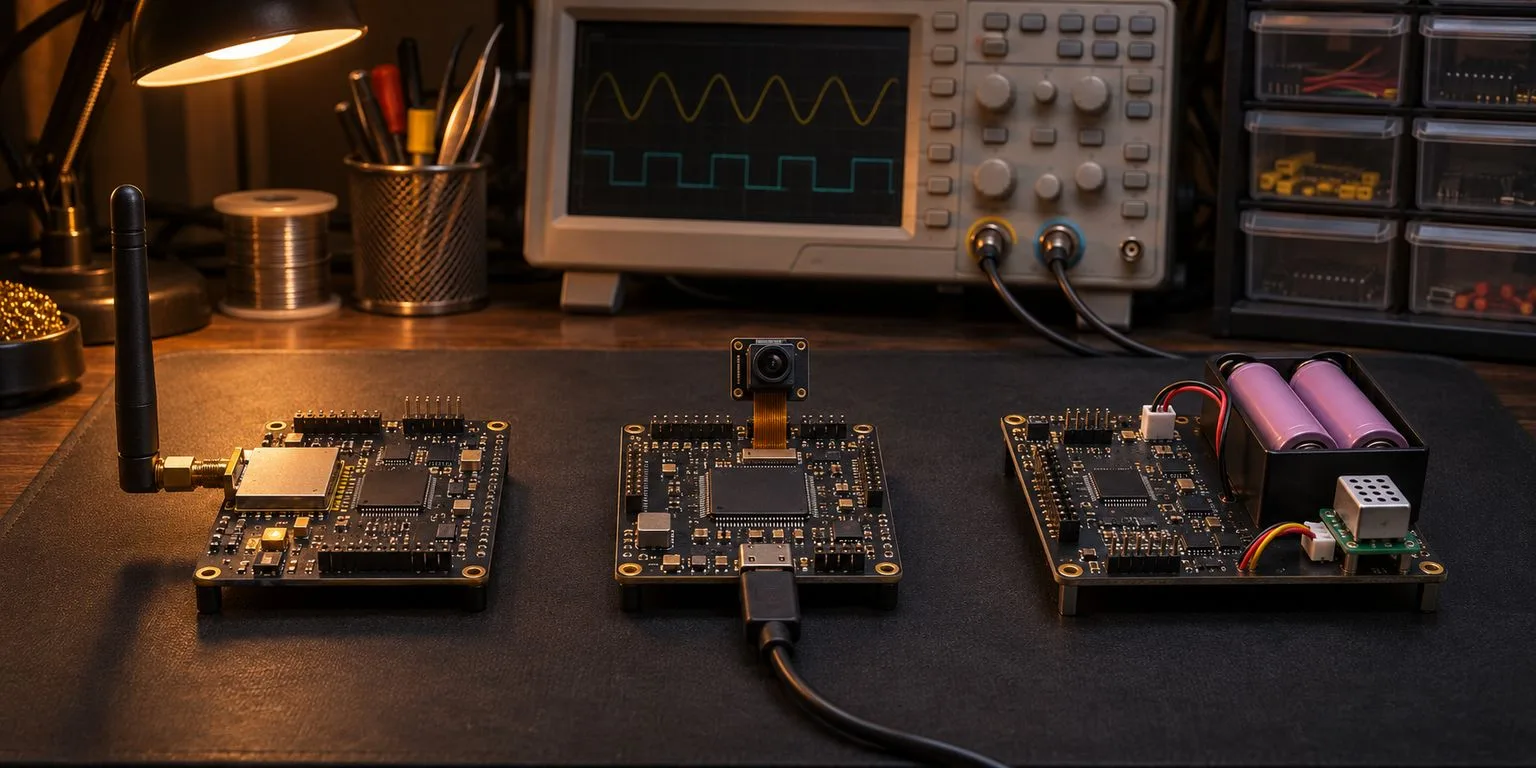
Choosing an ESP32 for a connected product starts with the workload, not a ranking of part numbers. This ESP32 chip comparison puts the ESP32-C6, ESP32-C5 and ESP32-S3 against the constraints that decide a board design: radio bands, local processing, interfaces, sleep behaviour and the state of the development stack. The right question is which requirement makes a candidate unsuitable, not which specification looks largest on a slide.
Start from the requirement, not the part number
Write down the required radio protocols and the actual access points in the deployment environment. Then identify the computation that must run locally, the peripherals that cannot be moved off-chip, the expected sleep cycle and the firmware stack that the team can maintain. Treat a development board as a demonstration of the silicon, not a complete answer to a product specification.
Before comparing numbers, note the sources: the current Espressif series datasheets for each chip. Numbers below are chip-family headline specifications; pin access and memory differ with packaging and modules. The vendor's C6 datasheet, C5 datasheet, and S3 datasheet should be checked against the exact order code before schematic release.
| Requirement | ESP32-C6 | ESP32-C5 | ESP32-S3 |
|---|---|---|---|
| Main CPU architecture and cores | Single RISC-V | Single RISC-V | Dual Xtensa LX7 |
| Maximum main clock | 160 MHz | 240 MHz | 240 MHz |
| On-chip SRAM | 512 KB HP + 16 KB LP | 384 KB HP + 16 KB LP | 512 KB |
| Wi-Fi | Wi-Fi 6, 2.4 GHz | Wi-Fi 6, 2.4 and 5 GHz | Wi-Fi 4, 2.4 GHz |
| Bluetooth LE | Bluetooth 5 LE | Bluetooth LE, certified to Core 6.0 | Bluetooth 5 LE |
| IEEE 802.15.4 | Yes | Yes | No |
| USB | USB Serial/JTAG, not USB OTG | USB Serial/JTAG, not USB OTG | USB OTG and USB Serial/JTAG |
| Camera/LCD interface | No dedicated camera/LCD interface | No dedicated camera/LCD interface | Camera and LCD interfaces |
| Low-power processor | LP RISC-V | LP RISC-V | ULP coprocessor |
| Maximum programmable GPIO | Up to 30, package dependent | Up to 29 | Up to 45, package dependent |
The table is a selection filter, not a substitute for pin-mux, clock, flash and power review. Where a package bonds out fewer pins, or a module reserves pins for flash or PSRAM, usable GPIO may be markedly lower than the silicon maximum. The S3's memory expansion options are particularly relevant when buffering image data.
Connectivity: 2.4 GHz Wi-Fi 6, dual-band Wi-Fi 6, or Wi-Fi 4 with more CPU
The C6 offers 2.4 GHz Wi-Fi 6, Bluetooth LE and IEEE 802.15.4 for Thread or Zigbee. The C5 adds 5 GHz Wi-Fi to that general connectivity mix. Of these three, only C5 supports 5 GHz Wi-Fi. An installation with a crowded 2.4 GHz band and a validated 5 GHz network can have a concrete reason to choose it.
Neither IEEE 802.15.4 support nor a standards logo means continuous simultaneous full-duty traffic on all protocols. Coexistence schedules access to shared radio resources. A Thread border-router architecture, for example, needs a realistic throughput and latency budget for Wi-Fi and the 802.15.4 network, and may need a different topology or an additional radio. Validate the RF coexistence mode on the intended ESP-IDF release.
The S3 instead provides Wi-Fi 4 on 2.4 GHz and Bluetooth LE. There is no IEEE 802.15.4 radio in the S3. A Thread or Zigbee device built around it needs an external 802.15.4 transceiver and the accompanying firmware integration. It should not be specified as a native Thread end device.
Compute: single RISC-V core vs dual Xtensa LX7
C6 and C5 use a high-performance RISC-V core, with separate low-power processing resources. S3 uses dual Xtensa LX7 cores and vector-oriented instructions that can help specific local DSP, UI and embedded inference workloads. Two cores do not double throughput by default; memory, scheduling and supported libraries decide whether work can run concurrently.
A sensor node that samples periodically, transforms readings and sends compact messages may not benefit from the S3's compute options. A device that must manipulate frames, animate a display or run suitable on-device inference may. Model execution must be measured on the candidate, including memory footprint, not inferred from core count. See when on-device inference is justified.
Peripherals, I/O and memory
USB OTG is a material differentiator. A USB Serial/JTAG controller is convenient for flashing and debugging, but it is not equivalent to running a USB host or implementing arbitrary USB-device functions. S3 is the candidate when the actual specification requires USB OTG.
Camera capture and LCD interfaces also point towards S3. Verify the camera or panel pin map, DMA and external memory demands on the chosen module before assuming a dev-board demonstration can be reproduced in a smaller enclosure. C6 and C5 still expose useful serial, SPI, I2C and other control interfaces, but they are not interchangeable with a dedicated camera/LCD interface.
Flash and PSRAM variants matter. Integrated memory and PSRAM availability depend on the orderable chip or module; flash pins may be unavailable for general signals. A datasheet maximum GPIO number is not a netlist budget. Review boot-strapping pins and external circuitry early. This is part of production readiness, not a late PCB cleanup.
Low power and the LP core
The C6 and C5 include low-power RISC-V processors designed for selected tasks while the main processor is inactive. S3 offers ULP processing for limited sensing and wake-oriented work. None makes the whole product low-power merely by existing on the die.
What matters is the actual sleep state, supported low-power peripherals, wake sources, radio connection strategy and consumption of the entire board. A development kit's regulator and status LEDs can dominate a measurement. For a battery device, test the expected sampling-to-transmission cycle and account for reconnection, sensing and recovery, rather than comparing a single sleep-current line.
Software and supply maturity
As checked on 6 November 2026, Espressif's ESP-IDF 6.0 release announcement describes ESP32-C5 as newly fully supported, graduating from preview support. Its chip family is also identified as being in mass production in Espressif's contemporary release information; that is not evidence of inventory for a particular module or distributor. Confirm order-code availability with the supply chain. ESP-IDF 6.0 release announcement; ESP-IDF compatibility information.
C6 and S3 have longer-established ESP-IDF support, but current support still depends on silicon revision. The compatibility matrix is a better authority than a blog's generic claim that every board works. Arduino integration, ESPHome features, debugging tools and third-party drivers must be checked independently for the selected release. Full ESP-IDF support does not certify every library or module example.
Selection scenarios
Dual-band Wi-Fi product in congested premises: choose C5. The required connection to a 5 GHz access point excludes C6 and S3, which are 2.4 GHz only. Verify regional channels and antenna performance before committing.
Camera capture device: choose S3. A dedicated camera interface is the deciding requirement; C6 and C5 have no camera/LCD interface, which excludes them.
USB host accessory or gateway: choose S3. The product must act as a USB host. C6 and C5 offer USB Serial/JTAG only, not USB OTG, which excludes them.
Local DSP or small inference workload with a display: choose S3 when measurements show the work needs two cores and vector instructions. C6 and C5 each have a single high-performance core, which excludes them for that requirement; measure before assuming the S3 is enough.
Battery-powered Zigbee or Matter-over-Thread end device: start with C6. Native IEEE 802.15.4 excludes S3. It does not exclude C5, which also has an 802.15.4 radio, so the choice between C6 and C5 here is a project-level trade (5 GHz need, cost, availability, software maturity), not a single-spec exclusion.
What none of the three solves
An Ethernet-first industrial gateway may be better served by another family or an external interface. High-resolution video processing can exceed these devices' practical memory and compute budgets. Border-router requirements with demanding concurrent RF duties deserve an architecture test before a single-chip commitment.
Moving from a dev board to a reliable product requires supply qualification, EMC work, power measurement, a reproducible firmware toolchain, security choices and a board design that does not accidentally consume essential pins. Continue with from dev board to product. The selection decision is a constrained engineering choice, not a universal ranking.